In this post I will be showing you how its possible to use different paths between your PE routers on a per VRF basis.
This is very useful if you have customers you want to “steer” away from your normal traffic flow between PE routers.
For example, this could be due to certain SLA’s.
For example, this could be due to certain SLA’s.
I will be using the following topology to demonstrate how this can be done:
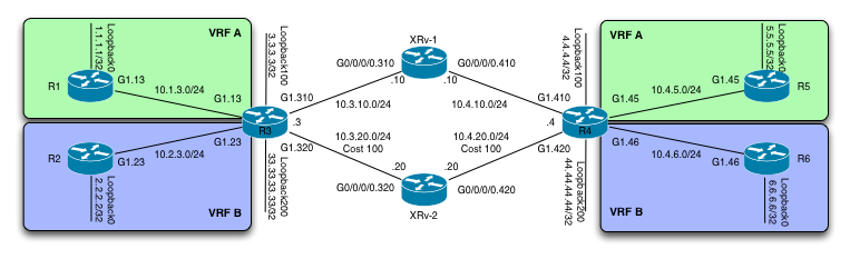
A short walkthrough of the topology is in order.
In the service provider core we have 4 routers. R3, XRv-1, XRv-2 and R4. R3 and R4 are IOS-XE based routers and XRv-1 and XRv-2 are as the name implies, IOS-XR routers. There is no significance attached to the fact that im running two XR routers. Its simply how I could build the required topology.
The service provider is running OSPF as the IGP, with R3 and R4 being the PE routers for an MPLS L3 VPN service. On top of that, LDP is being used to build the required LSP’s. The IGP has been modified to prefer the northbound path (R3 -> XRv-1 -> R4) by increasing the cost of the R3, XRv-2 and R4 to 100.
So by default, traffic between R3 and R4 will flow northbound.
We can easily verify this:
1
2
3
4
5
6
| R3#traceroute 4.4.4.4Type escape sequence to abort.Tracing the route to 4.4.4.4VRF info: (vrf in name/id, vrf out name/id) 1 10.3.10.10 [MPLS: Label 16005 Exp 0] 16 msec 1 msec 1 msec 2 10.4.10.4 1 msec * 5 msec |
And the reverse path is the same:
1
2
3
4
5
6
| R4#traceroute 3.3.3.3Type escape sequence to abort.Tracing the route to 3.3.3.3VRF info: (vrf in name/id, vrf out name/id) 1 10.4.10.10 [MPLS: Label 16000 Exp 0] 3 msec 2 msec 0 msec 2 10.3.10.3 1 msec * 5 msec |
Besides that traffic flow the desired way, we can see we are using label switching between the loopbacks. Exactly what we want in this type of setup.
On the customer side, we have 2 customers, Customer A and Customer B. Each of them has 2 sites, one behind R3 and one behind R4. Pretty simple. They are all running EIGRP between the CE’s and the PE’s.
Beyond this we have MPLS Traffic Engineering running in the service core as well. Specifically we are running a tunnel going from R3’s loopback200 (33.33.33.33/32) towards R4’s loopback200 (44.44.44.44/32). This has been accomplished by configuring an explicit path on both R3 and R4.
Lets verify the tunnel configuration on both:
On R3:
1
2
3
4
5
6
7
8
9
10
11
12
13
14
15
| R3#sh ip explPATH NEW-R3-TO-R4 (strict source route, path complete, generation 8) 1: next-address 10.3.20.20 2: next-address 10.4.20.4R3#sh run int tunnel10Building configuration...Current configuration : 180 bytes!interface Tunnel10 ip unnumbered Loopback200 tunnel mode mpls traffic-eng tunnel destination 10.4.20.4 tunnel mpls traffic-eng path-option 10 explicit name NEW-R3-TO-R4end |
And on R4:
1
2
3
4
5
6
7
8
9
10
11
12
13
14
15
| R4#sh ip explPATH NEW-R4-TO-R3 (strict source route, path complete, generation 4) 1: next-address 10.4.20.20 2: next-address 10.3.20.3R4#sh run int tun10Building configuration...Current configuration : 180 bytes!interface Tunnel10 ip unnumbered Loopback200 tunnel mode mpls traffic-eng tunnel destination 10.3.20.3 tunnel mpls traffic-eng path-option 10 explicit name NEW-R4-TO-R3end |
On top of that we have configured a static route on both R3 and R4, to steer traffic for each others loopback200’s down the tunnel:
1
2
3
4
5
| R3#sh run | incl ip routeip route 44.44.44.44 255.255.255.255 Tunnel10R4#sh run | incl ip routeip route 33.33.33.33 255.255.255.255 Tunnel10 |
Resulting in the following RIB’s:
1
2
3
4
5
6
7
8
9
10
11
12
13
| R3#sh ip route 44.44.44.44Routing entry for 44.44.44.44/32 Known via "static", distance 1, metric 0 (connected) Routing Descriptor Blocks: * directly connected, via Tunnel10 Route metric is 0, traffic share count is 1 R4#sh ip route 33.33.33.33Routing entry for 33.33.33.33/32 Known via "static", distance 1, metric 0 (connected) Routing Descriptor Blocks: * directly connected, via Tunnel10 Route metric is 0, traffic share count is 1 |
And to test out that we are actually using the southbound path (R3 -> XRv-2 -> R4), lets traceroute between the loopbacks (loopback200):
on R3:
1
2
3
4
5
6
| R3#traceroute 44.44.44.44 so loopback200Type escape sequence to abort.Tracing the route to 44.44.44.44VRF info: (vrf in name/id, vrf out name/id) 1 10.3.20.20 [MPLS: Label 16007 Exp 0] 4 msec 2 msec 1 msec 2 10.4.20.4 1 msec * 3 msec |
and on R4:
1
2
3
4
5
6
| R4#traceroute 33.33.33.33 so loopback200Type escape sequence to abort.Tracing the route to 33.33.33.33VRF info: (vrf in name/id, vrf out name/id) 1 10.4.20.20 [MPLS: Label 16008 Exp 0] 4 msec 1 msec 1 msec 2 10.3.20.3 1 msec * 3 msec |
This verifies that we have our two unidirectional tunnels and that communication between the loopback200 interfaces flows through the southbound path using our TE tunnels.
So lets take a look at the very simple BGP PE configuration on both R3 and R4:
R3:
1
2
3
4
5
6
7
8
9
10
11
12
13
14
15
16
17
18
19
20
21
| router bgp 100 bgp log-neighbor-changes no bgp default ipv4-unicast neighbor 4.4.4.4 remote-as 100 neighbor 4.4.4.4 update-source Loopback100 ! address-family ipv4 exit-address-family ! address-family vpnv4 neighbor 4.4.4.4 activate neighbor 4.4.4.4 send-community extended exit-address-family ! address-family ipv4 vrf A redistribute eigrp 100 exit-address-family ! address-family ipv4 vrf B redistribute eigrp 100 exit-address-family |
and R4:
1
2
3
4
5
6
7
8
9
10
11
12
13
14
15
16
17
18
19
20
21
| router bgp 100 bgp log-neighbor-changes no bgp default ipv4-unicast neighbor 3.3.3.3 remote-as 100 neighbor 3.3.3.3 update-source Loopback100 ! address-family ipv4 exit-address-family ! address-family vpnv4 neighbor 3.3.3.3 activate neighbor 3.3.3.3 send-community extended exit-address-family ! address-family ipv4 vrf A redistribute eigrp 100 exit-address-family ! address-family ipv4 vrf B redistribute eigrp 100 exit-address-family |
From this output, we can see that we are using the loopback100 interfaces for the BGP peering. As routing updates comes in from one PE, the next-hop will be set to the remote PE’s loopback100 interface. This will then cause the transport-label to be one going to this loopback100 interface.
A traceroute from R1’s loopback0 interface to R5’s loopback0 interface, will show us the path that traffic between each site in VRF A (Customer A) will take:
R1:
1
2
3
4
5
6
7
8
| R1#traceroute 5.5.5.5 so loo0Type escape sequence to abort.Tracing the route to 5.5.5.5VRF info: (vrf in name/id, vrf out name/id) 1 10.1.3.3 1 msec 1 msec 0 msec 2 10.3.10.10 [MPLS: Labels 16005/408 Exp 0] 6 msec 1 msec 10 msec 3 10.4.5.4 [MPLS: Label 408 Exp 0] 15 msec 22 msec 17 msec 4 10.4.5.5 18 msec * 4 msec |
and lets compare that to what R3 will use as the transport label to reach R4’s loopback100 interface:
1
2
3
4
5
6
7
8
9
10
11
12
13
| R3#sh mpls forLocal Outgoing Prefix Bytes Label Outgoing Next HopLabel Label or Tunnel Id Switched interface300 Pop Label 10.10.10.10/32 0 Gi1.310 10.3.10.10301 Pop Label 10.4.10.0/24 0 Gi1.310 10.3.10.10302 Pop Label 20.20.20.20/32 0 Gi1.320 10.3.20.20303 16004 10.4.20.0/24 0 Gi1.310 10.3.10.10304 [T] Pop Label 44.44.44.44/32 0 Tu10 point2point305 16005 4.4.4.4/32 0 Gi1.310 10.3.10.10310 No Label 1.1.1.1/32[V] 2552 Gi1.13 10.1.3.1311 No Label 10.1.3.0/24[V] 0 aggregate/A312 No Label 2.2.2.2/32[V] 2552 Gi1.23 10.2.3.2313 No Label 10.2.3.0/24[V] 0 aggregate/B |
We can see that this matches up being 16005 (going to XRv-1) through the northbound path.
This begs the question, how do we steer our traffic through the southbound path using the loopback200 instead, when the peering is between loopback100’s?
Well, thankfully IOS has it covered. Under the VRF configuration for Customer B (VRF B), we have the option of setting the loopback interface of updates sent to the remote PE:
On R3:
1
2
3
4
5
6
7
8
| vrf definition B rd 100:2 ! address-family ipv4 route-target export 100:2 route-target import 100:2 bgp next-hop Loopback200 exit-address-family |
and the same on R4:
1
2
3
4
5
6
7
8
| vrf definition B rd 100:2 ! address-family ipv4 route-target export 100:2 route-target import 100:2 bgp next-hop Loopback200 exit-address-family |
This causes the BGP updates to contain the “correct” next-hop:
R3:
1
2
3
4
5
6
| R3#sh bgp vpnv4 uni vrf B | beg Route DisRoute Distinguisher: 100:2 (default for vrf B) *> 2.2.2.2/32 10.2.3.2 130816 32768 ? *>i 6.6.6.6/32 44.44.44.44 130816 100 0 ? *> 10.2.3.0/24 0.0.0.0 0 32768 ? *>i 10.4.6.0/24 44.44.44.44 0 100 0 ? |
44.44.44.44/32 being the loopback200 of R4, and on R4:
1
2
3
4
5
6
| R4#sh bgp vpnv4 uni vrf B | beg Route DisRoute Distinguisher: 100:2 (default for vrf B) *>i 2.2.2.2/32 33.33.33.33 130816 100 0 ? *> 6.6.6.6/32 10.4.6.6 130816 32768 ? *>i 10.2.3.0/24 33.33.33.33 0 100 0 ? *> 10.4.6.0/24 0.0.0.0 0 32768 ? |
Lets check out whether this actually works or not:
1
2
3
4
5
6
7
8
| R2#traceroute 6.6.6.6 so loo0Type escape sequence to abort.Tracing the route to 6.6.6.6VRF info: (vrf in name/id, vrf out name/id) 1 10.2.3.3 1 msec 1 msec 0 msec 2 10.3.20.20 [MPLS: Labels 16007/409 Exp 0] 4 msec 1 msec 10 msec 3 10.4.6.4 [MPLS: Label 409 Exp 0] 15 msec 16 msec 17 msec 4 10.4.6.6 19 msec * 4 msec |
Excellent! – We can see that we are indeed using the southbound path. To make sure we are using the tunnel, note the transport label of 16007, and compare that to:
R3:
1
2
3
4
5
6
7
8
9
10
11
12
13
14
15
16
17
18
19
20
| R3#sh mpls traffic-eng tun tunnel 10Name: R3_t10 (Tunnel10) Destination: 10.4.20.4 Status: Admin: up Oper: up Path: valid Signalling: connected path option 10, type explicit NEW-R3-TO-R4 (Basis for Setup, path weight 200) Config Parameters: Bandwidth: 0 kbps (Global) Priority: 7 7 Affinity: 0x0/0xFFFF Metric Type: TE (default) AutoRoute: disabled LockDown: disabled Loadshare: 0 [0] bw-based auto-bw: disabled Active Path Option Parameters: State: explicit path option 10 is active BandwidthOverride: disabled LockDown: disabled Verbatim: disabled InLabel : - OutLabel : GigabitEthernet1.320, 16007 Next Hop : 10.3.20.20 |
I have deleted alot of non-relevant output, but pay attention to the Outlabel, which is indeed 16007.
So that was a quick walkthrough of how easy it is to accomplish the stated goal once you know about that nifty IOS command.
I hope its been useful to you.
No comments:
Post a Comment